
Trans inductor voltage regulators, occasionally referred to as transient load voltage regulators, (TLVRs) use coupled inductors with an additional secondary winding to create a series-connected secondary loop, allowing all phases to react simultaneously to load changes. That enables TLVRs to support the extreme power demands of GPUs in AI datacenters, and as detailed below, they cost less than conventional multi-phase designs.
The topology excels at delivering faster transient response, significantly reduced output voltage droop, and higher power density. It does all that and reduces the need for large output capacitor banks compared to traditional multiphase buck regulators while still supplying 1,000 A at low voltages to power AI GPUs. A tough job.
The alternative name of transient load voltage regulator is descriptive of the purpose of a TLVR, but ‘trans inductor voltage regulator’ is a better description of how the topology works.
What’s a trans inductor?
TLVRs build on the basic concept of a multi-phase buck converter. The single-winding inductor is replaced by an inductor with two coupled windings. As in a multi-phase buck, the primary sides of each inductor are connected between the switch and the output.
The secondary windings are connected in a series loop. A key innovation is the addition of the compensating inductor (LC) that couples the inductors in the secondary loop to react essentially simultaneously to load transients (Figure 1).

TLVR performance
TLVRs were developed to handle the extreme load transients in AI datacenters that typically consist of clusters of GPUs. During common AI operations like large language model (LLM) training and inference, power demand can ramp up and down rapidly. Power transients during inference can be particularly challenging.
Depending on the circumstances, those power surges and dips can happen in <200 milliseconds. In extreme cases, transients of a few microseconds can reach 90% of peak current. That’s tough for any power system to handle.
During load transients, LC causes the load to be shared across the secondaries. That significantly improves the transient response compared to a multiphase topology. It’s generally claimed that (optimized) TLVRs can deliver a 4x improvement in transient response.
The key is striking a balance between ripple and transient response. A smaller LC can support faster slew rates. Ripple also increases at faster slew rates. The value of LC is usually determined by the maximum allowable current ripple (Figure 2).
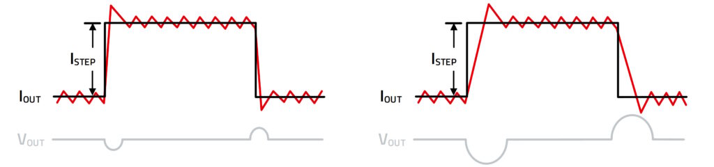
Another factor in TLVR performance is the ratio between the magnetizing inductance and the leakage inductance of LC. Performance improves when magnetizing inductance is high and leakage inductance is low. Magnetizing inductance is a key factor in reduced ripple current, and low leakage inductance supports faster transient response.
Some other performance boosts from replacing conventional multi-phase power with TLVRs include:
- Higher power density and improved efficiency.
- Simplified support for 48 Vdc power distribution architectures.
- Improved thermal performance.
- Superior flexibility and scalability.
The use of TLVR power enables output capacitance reductions of 40% or more, even accounting for the addition of LC. That results in a significantly smaller solution size. Less capacitance also reduces parts count and reduces costs. The cost savings are more than enough to pay for the increased cost of the coupled inductors. That lowers overall solution cost.
What does a trans inductor look like?
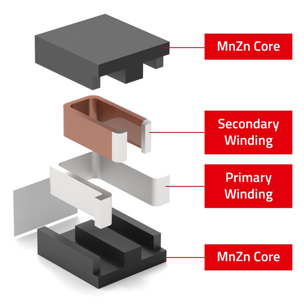
Just because it’s better doesn’t mean it can be bigger. The size and shape of most TLVR inductors is like that of the ferrite-core inductors used in conventional multi-phase buck converters.
The primary difference is their nested coil structure. In a TLVR inductor, the secondary winding is inside the primary.
The bottom land patterns are designed to enable the use of both TLVR and conventional voltage regulators on a common circuit board layout. The air gap in a TLVR inductor must be tightly controlled to deliver the precise coupling between the primary and secondary to control the AC flux and core saturation. To meet the required performance and size requirements, TLVR inductors have simple constructions (Figure 3):
- Manganese-zinc (MnZn) is the preferred core material and delivers high permeability.
- The external winding is made using flat wire without isolation. It’s optimized for high currents and low DC resistance.
- The internal winding also uses flat wire. It’s isolated to support safe and reliable operation in demanding high-power applications.
Summary
TLVR technology was developed to support high transient loads in AI datacenters. They also deliver benefits related to efficiency, thermal management, scalability, and other factors. TLVR power solutions are more complex compared with traditional multi-phase options, but they use fewer components due to the lower output capacitance needs. The significant reduction in output capacitance pays for the increased cost of the coupled inductors and leaves additional savings, resulting in lower overall solution costs.
References
Demystifying dual winding TLVR inductors, Eaton
Infineon presents first high-density trans-inductance voltage regulator (TLVR) power modules optimized for AI data centers, Infineon
Introduction to the Trans-Inductor Voltage Regulator (TLVR), Texas Instruments
TLVR Inductors for Server Power Supply Circuits, TDK
The Trans-Inductor Voltage Regulator (TLVR) Solution, Yaego
Trans-Inductor Voltage Regulator (TLVR) Inductors, Abracon
Trans-Inductor Voltage Regulators outperform traditional Multi-Phase Voltage Regulators, Würth Elektronik
Transinductor Voltage Regulator High Voltage Considerations, Analog Devices
Voltage Regulation in Distribution Systems with Data Center Loads, arXiv
Related EEWorld Online content
How do ML and AI work in power conversion? part 1
What are key considerations for USB Type-C ESD protection?
How can AI enhance DVFS in processor power management?
What tools are there to reduce AI power consumption?
How is power limiting the adoption of physical artificial intelligence in humanoid robotics?